Mixing in T-Junctions: Momentum Ratios, Vortices, and Design Insights
Published on: September 8, 2025
The Big Question: Which Gas Goes Where?
When you look at a T-junction, the most immediate design question is often: “How do we know from which end of the T-junction we should flow which gas?”
If you have a fast, light gas and a slow, heavy gas, which one belongs in the main pipe, and which one goes in the branch side? The humble T-junction is everywhere - in chemical plants, natural gas pipelines, and even microfluidic devices. But figuring out the best way to mix two streams isn’t just about plumbing; it’s a classic jet-in-crossflow (JICF) physics problem.
When a branch jet enters a main crossflow, the resulting interaction spawns a series of vortical structures and turbulent mixing processes that dictate mixing efficiency.
Defining the Momentum Ratio
In most of the literature, the momentum flux ratio is defined as jet momentum ÷ crossflow momentum.
Here, I flip that definition to emphasize the competition between the crossflow and the branch jet:
- Low J: jet dominates (strong penetration).
- High J: crossflow dominates (jet bends, attaches to wall).
This framing makes the physics of a T-junction a momentum tug-of-war between crossflow and branch jet.
Flow Physics: The Vortices That Do the Work
Experiments using PIV and PLIF (Pan et al., 2001) and LES simulations (Salewski et al., 2008) reveal that a handful of coherent structures dominate mixing:
- Counter-Rotating Vortex Pair (CVP): the kidney-shaped signature of JICF. The CVP folds the scalar interface, entrains crossflow into the jet, and drives macro-mixing.
- Shear-Layer Vortices: Kelvin - Helmholtz instabilities at the jet edge - critical for near-field entrainment.
- Horseshoe and Wake Vortices: wrap around the jet base and trail downstream, adding unsteadiness and small-scale stirring (Zhang & Yang, 2017).
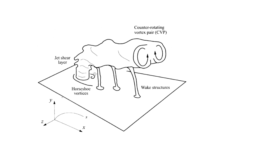
Figure 1: Schematic from presentation showing CVP, shear-layer vortices, and horseshoe vortices around the branch jet.
Flow Regimes vs. Momentum Balance
Classic experiments by Kok & van der Wal (1996) (Kok & van der Wal, 1996) revealed three distinct flow regimes that arise from the competition between the branch jet and the main crossflow. In their study, the momentum ratio was defined as :
\[M_R = \frac{\rho_\text{jet} U_\text{jet}^2}{\rho_\text{main} U_\text{main}^2}\]where higher Mr corresponds to a stronger jet. In this post, I use the inverse convention,
\(J = \frac{\rho_\text{cross} U_\text{cross}^2}{\rho_\text{jet} U_\text{jet}^2} = \frac{1}{M_R}\) so that increasing J indicates a stronger crossflow (and weaker jet).
Figure 2 below, adapted from Kok & van der Wal (1996), shows the three canonical regimes as observed experimentally:
Wall-Jet Regime (high J, low M_R) - the crossflow dominates, bending the jet and causing it to attach to the wall downstream.
Deflected-Jet Regime (moderate J, moderate M_R) - the jet partially penetrates, forming a counter-rotating vortex pair (CVP) that drives efficient mixing.
Impinging-Jet Regime (low J, high M_R) - the jet momentum dominates, crossing the pipe and impinging on the opposite wall, producing intense but localized mixing.
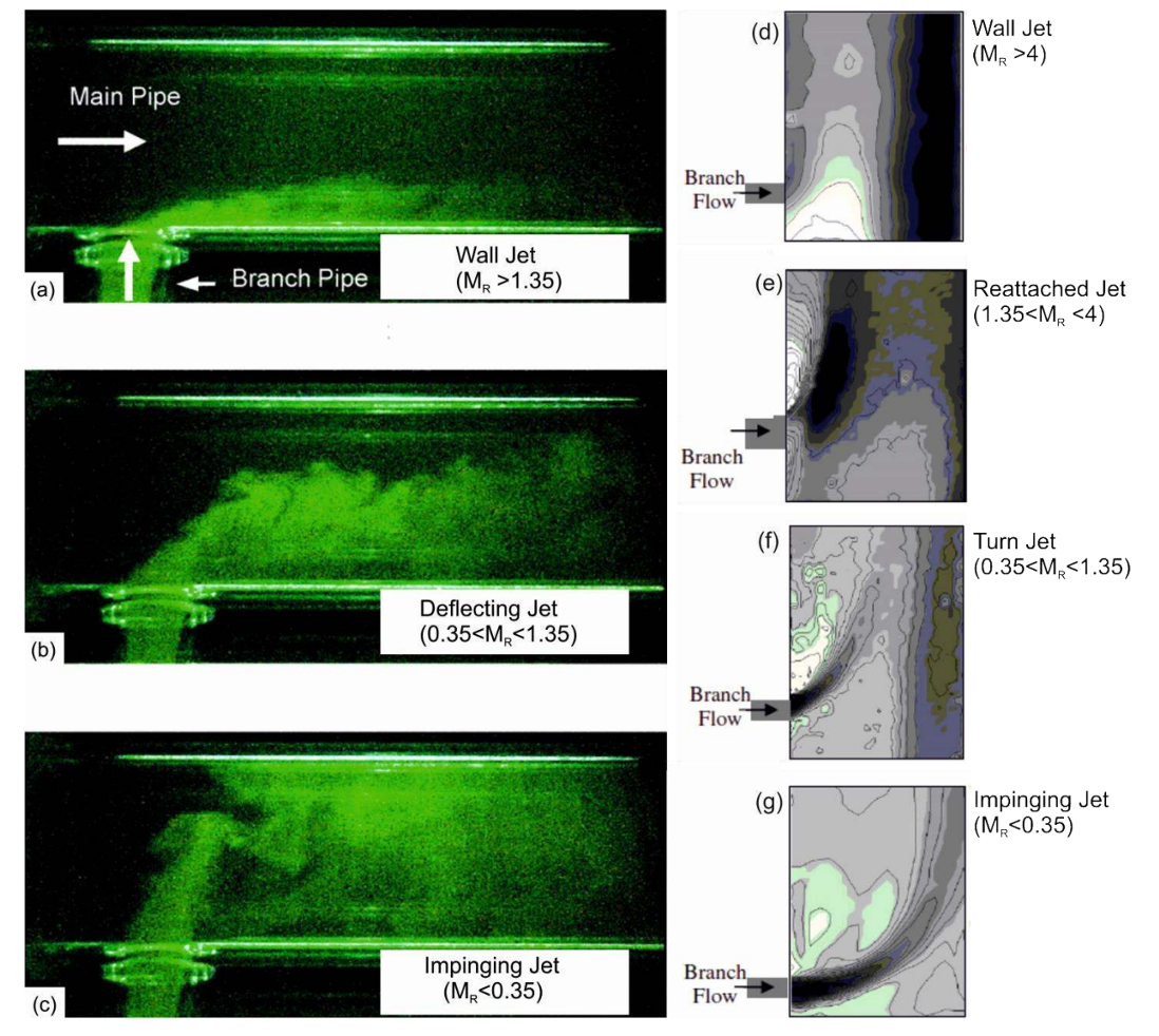
Figure 2. Flow regimes in T-junctions from Kok \& van der Wal (1996).
The authors define M_R as jet momentum over main pipe momentum; here J = 1/M_R, so the horizontal ordering (wall - deflected - impinging) corresponds to increasing jet strength and decreasing J.
To connect these experimental observations with my numerical work, Figure 3 below show COMSOL velocity - magnitude contours and streamlines at two representative conditions:
High J - crossflow-dominated case (N₂ = 3000 sccm, H₂ = 2000 sccm) The jet bends sharply and remains attached to the wall, matching the “wall-jet” behavior seen experimentally.
Moderate J - balanced momentum case (N₂ = 1457 sccm, H₂ = 500 sccm) The jet penetrates into the main stream and rolls up into a kidney-shaped CVP, consistent with the “deflected-jet” regime.
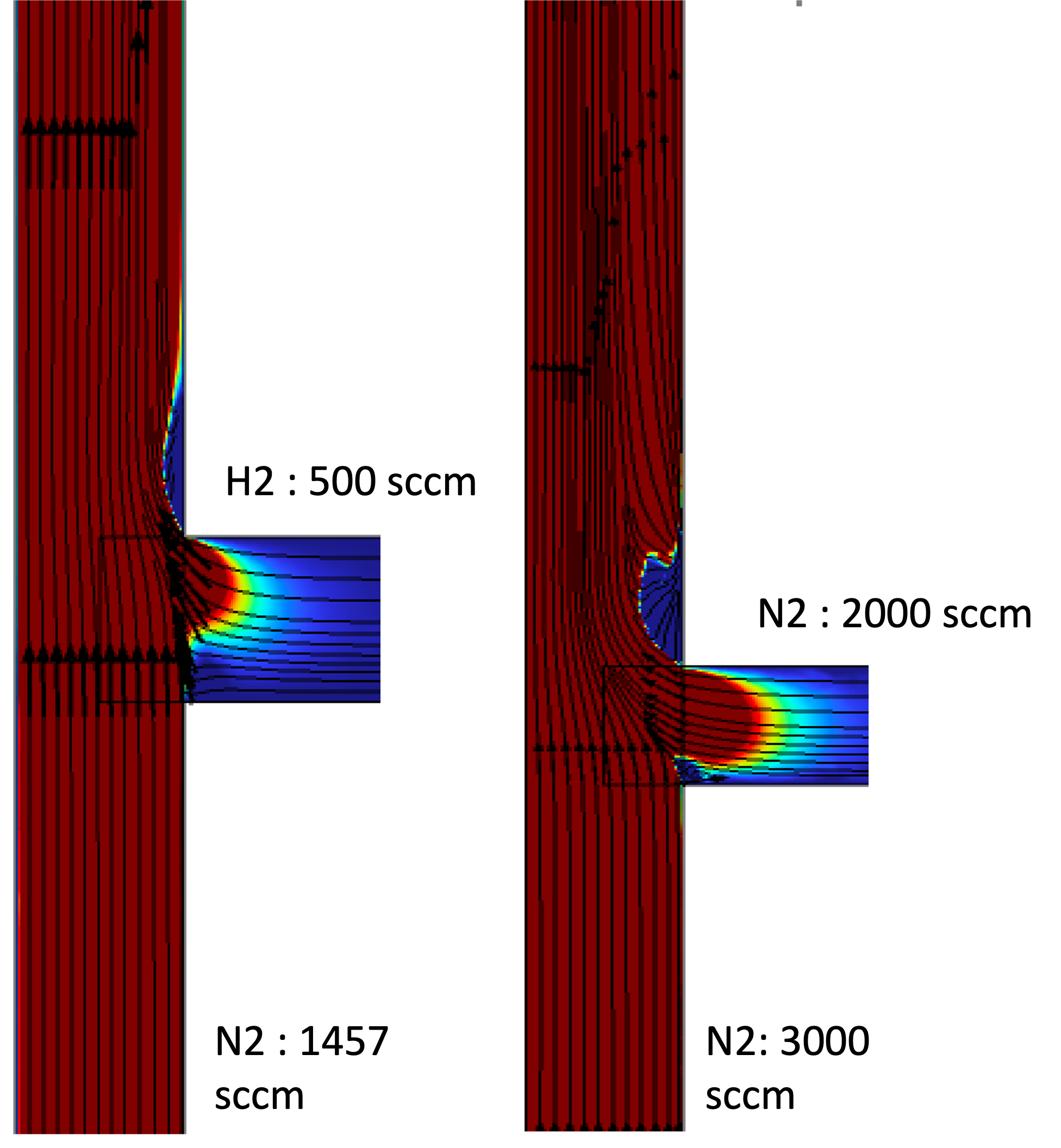
Figure 3. {High J} - crossflow-dominated case (N₂ = 3000 sccm, H₂ = 2000 sccm).
The jet bends sharply and remains attached to the wall, matching the “wall-jet” behavior seen experimentally.
{Moderate J} - balanced momentum case (N₂ = 1457 sccm, H₂ = 500 sccm).
The jet penetrates into the main stream and rolls up into a kidney-shaped CVP, consistent with the “deflected-jet” regime.
⚠️ Note: My COMSOL simulations were parameterized by jet-to-crossflow velocity ratios, not explicit momentum ratios. Still, the qualitative transitions align directly with the regimes mapped in literature against J.
Mixing Metrics: From CV to Mixing Length
While the flow regimes describe how the jet and crossflow interact, the actual efficiency of mixing can be captured more quantitatively.
A common measure is the Coefficient of Variation (COV), which compares the standard deviation of concentration to its mean value:
Here, C is the local concentration, C̄ is the mean value across the cross-section, and σ_C is the standard deviation.
A perfectly mixed flow has COV = 0, while a mixture is considered ``uniform’’ when COV ≤ 0.05 (Sun et al., 2020).
In a T-junction, COV decreases gradually along the main channel as the jet entrains and diffuses into the crossflow. The rate at which this happens depends strongly on the momentum ratio J:
High J - the crossflow dominates, and the jet hugs the wall. Mixing is slow and requires a long downstream length. Moderate J - the jet and crossflow have comparable momentum. The CVP folds the interface efficiently, leading to faster homogenization. Low J - the jet dominates and penetrates fully across the pipe, resulting in rapid but locally intense mixing.
Hydrogen blending studies show a similar dependence on momentum ratio (Tian et al.).
At 10% H₂, the required mixing length is roughly 100D, while at 25% H₂ it drops to about 21D.
This same trend appears in my COMSOL simulations - stronger jets (lower J) mix quickly, whereas crossflow-dominated configurations (higher J) require a much longer channel to achieve uniformity.
Design Lessons
- Momentum ratio is the master knob. More than Reynolds number or angle tweaks, the momentum balance sets the mixing regime.
- Trade-offs are fundamental. Impingement → fastest mixing, but highest ΔP and strongest thermal fluctuations (Thermal mixing in T-junctions).
- Geometry tweaks help, but momentum dominates. Injection angle, upstream elbows, and branch protrusion improve efficiency (Ansah et al., 2024).
- Density differences complicate things. Light gases stratify unless jet momentum is sufficient (Mixing of dense/light gases model).
Closing Thoughts
A T-junction is deceptively simple but hides rich vortex dynamics.
By reframing the momentum ratio as crossflow vs. jet, the regimes become intuitive: the outcome depends on which stream “wins” the momentum battle.
Even though my COMSOL simulations did not directly calculate J, the velocity-ratio sweeps clearly reproduce the same qualitative regimes reported in literature - making the physics vivid and bridging numerical work with experimental observations.
References
- Sun et al., Appl. Sci. 2020
- Pan et al., AIChE J. 2001
- Salewski et al., Flow Turb. Comb. 2008
- Kok & van der Wal, Univ. of Twente 1996
- Zhang & Yang, J. Propul. Power 2017
- Tian et al., Materials 2025
- Rimza et al., Case Stud. Therm. Eng. 2023
- Ansah et al., World J. Eng. Tech. 2024